Blog. And sometimes just whinging.
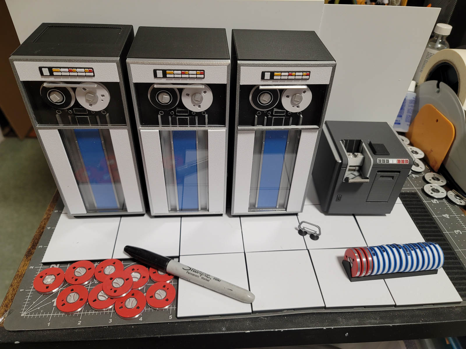
IBM 7090/7094 miniature replica – WIP
// November 16th, 2024 // Comments Off on IBM 7090/7094 miniature replica – WIP // 3D, miniature
A work in progress. Completed are the 729 tape drives and the card reader. Also shown, [faux] raised floor, tile puller, and tape rack. Working on a 7151 console, then processor and memory cabinets.
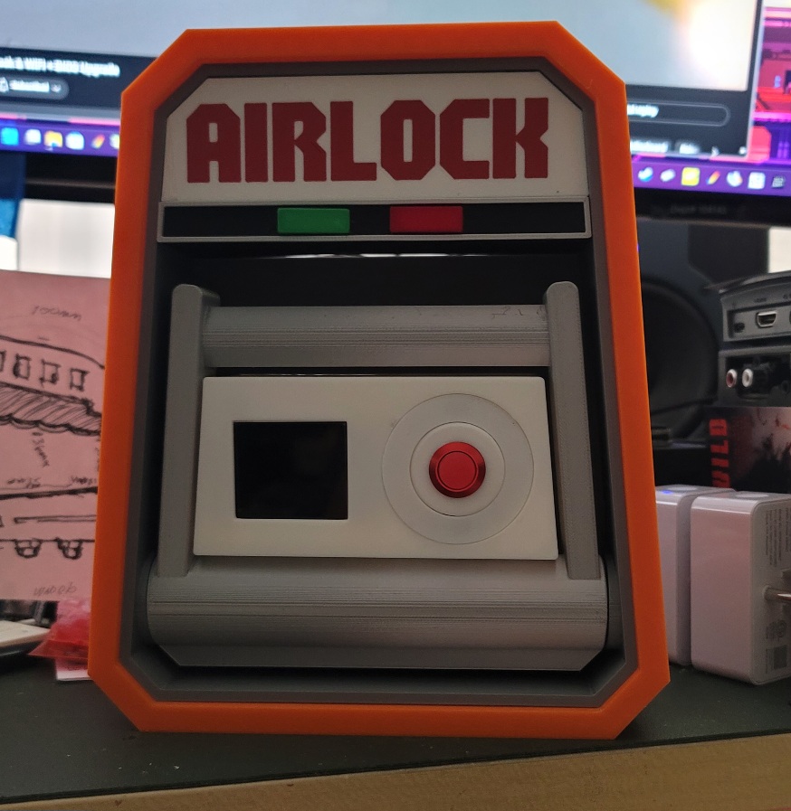
Airlock Interface – WIP
// November 16th, 2024 // Comments Off on Airlock Interface – WIP // Rambling
This is a new design with working handle, button, and display.
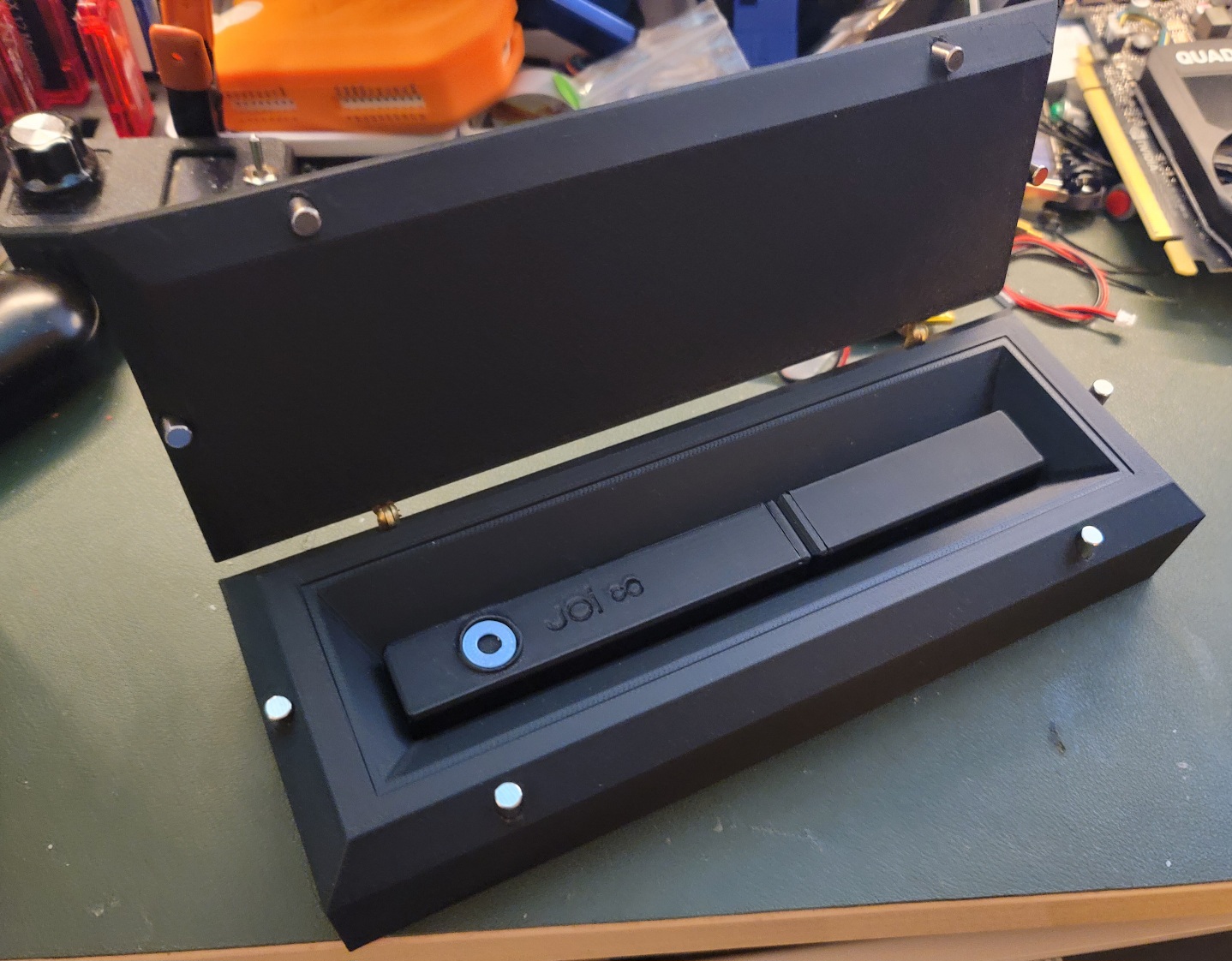
Joi Emanator and case – WIP
// November 16th, 2024 // Comments Off on Joi Emanator and case – WIP // 3D, props
Miniature guitar amps – WIP
// November 16th, 2024 // Comments Off on Miniature guitar amps – WIP // 3D
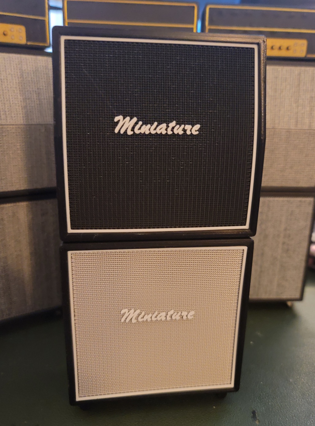
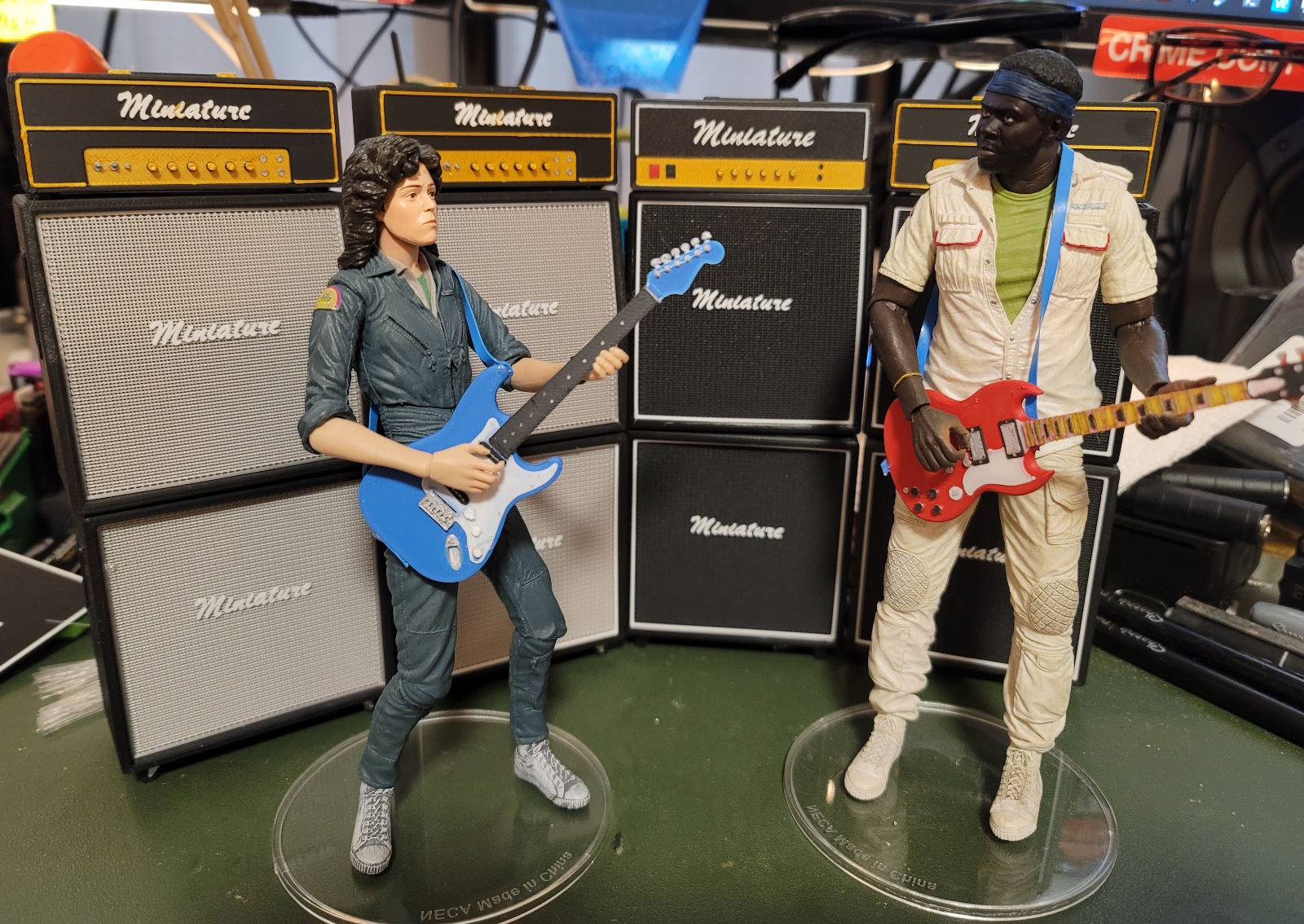
Guitars are not my design. Just some models I found online.
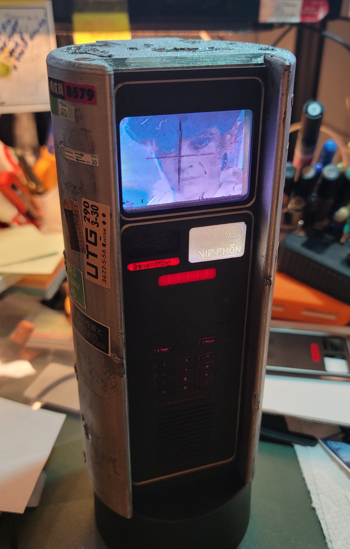
Vi-Phon scale replica – WIP
// November 16th, 2024 // Comments Off on Vi-Phon scale replica – WIP // 3D, props
Just a quick update and Sky Captain ray gun update
// April 24th, 2022 // Comments Off on Just a quick update and Sky Captain ray gun update // 3D, props
I have a slew of things I should post here and on https://skyfortress.studio but since it’s prominently displayed here, I wanted to post an update re: my Sky Captain (or Dex) ray gun model. I’ve made a lot of refinements and here’s the current build.
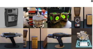
My prop replicas, let me show you them
// January 3rd, 2019 // Comments Off on My prop replicas, let me show you them // Uncategorized
You may be looking for http://skyfortress.studio/. Maybe. Maybe not.
You can find my Old School Video Games site at OSVG.net
You can find my (mostly Amiga-related) online store at OSVG Store
Something in the works – Sky Captain, Dex’s ray gun
// June 12th, 2016 // Comments Off on Something in the works – Sky Captain, Dex’s ray gun // 3D, props
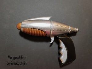
UPDATE: Here’s a pic of the assembled and finished version (plus stand).
UPDATE UPDATE: This now lives in Adam Savage’s cave. But I have made more since.

Sky Captain and the World of Tomorrow ray gun replica by Maggie McFee
So let me just get this confession out of the way.
I love Kerry Conran’s Sky Captain and the World of Tomorrow. I love it to death, warts and all. Roger Ebert said of the film, “It’s like a film that escaped from the imagination directly onto the screen, without having to pass through reality along the way.”
Well, the imagination in question could have been mine, if it hadn’t been Kerry and Kevin Conran’s. It speaks to me on a very deep level; It’s a film that could have been made just for me. I’m not old enough to remember film and radio serials, obviously, but I did grow up on a steady diet of SciFi — Doctor Who and Star Trek being staples of my diet and, of course, Star Wars — and that diet sometimes included old serials which played on a local TV station late at night as filler for the late night movie. I recall many a night sneaking out of bed to watch Flash Gordon or some other B&W treat quietly in the living room while my parents slept. Hey, they advertised them during the afternoon when I was watching cartoons, how could I resist? Later in life I developed a fascination with old radio serials as well and listened to countless hours of them.
Sky Captain was like a concentrated booster shot of all that: Giant robots, heroes in tricked out aircraft, swaggering female fighter aces, flying aircraft carriers… and ray guns. Sky Captain was a siren call to me in 2004. And there’s one prop from the film I’ve always wanted, in some form or other, but never have found: Dex’s ray gun. Sure, I have the ornament version, but that’s small consolation. Literally. So I decided it was time to make my own and got to modeling. I’ve printed a couple (you can see one here, but bear in mind this is a rough version) to test and hand fit and I’m still tweaking, but it’s about 95% done, I think. I’ve extended the nose cone a bit since I took this screen shot, but this is how the current model looks.
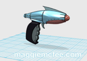
More soon as I’ll be building and painting a clean final version soon.
Prototyping and Printing
// May 21st, 2016 // Comments Off on Prototyping and Printing // art, props
I finally broke down and bought a grown-up 3D printer. My Prusa i3 was fine, as far as it went, but my growing envy of the nice (and giant) prints of Lulzbot TAZ 5 owners’s like James Bruton did me in. So I bought a Lulzbot TAZ 5 and added a FlexyDually dual extruder which allows me to print in normal materials from the primary head as well as flexible (such as Ninjaflex) and support materials from a second head. And I don’t regret it one bit. This machine is heaven. It’s like going from a motorcycle to a luxury car.
Speaking of printing, I’ve been designing/prototyping some props. More on all these later, but here’s a peek at what’s on deck at the moment.
 The first is a scratch-built Commlock (another Space: 1999 prop). I’m calling it a prototype in that the idea was to figure out how to build one well by building one at all. :) I have a screen and electronics for the next iteration using what I learned. This one, as will the next, was built from Plastruct sheets and tubing, some laser cut elements, 3D printed buttons with white-on-black label tape for the numbers.
Related, I just bought a Century Casting commlock off eBay, so I’ll build that later as well. But the scratch-builts are my first priority.

I’ve also been working on 3D modeling the Vulcan 65 grenade from the first Hellboy movie. I have a few additions to make on the internals and just finished making the top removable, but I’ve pretty happy with the overall design. I’ll make a couple more and then I may make a cast of it so I can make some resin versions. I plan to add LEDs to one or two of the later printed ones.
The lettering is done using waterslide decals I designed and printed in Photoshop.
 Yet another Hellboy prop I’m working on is Ilsa’s salt cellar, the one containing the tears of a thousand angels (or martyrs in the earlier script). This one has been all about modeling and learning to make a patina’d surface look right. I solid-modeled the base, legs and dome. The glass is just a 7″ glass vase. It’s not exactly the right size. It’s 7″ high and about 3.2″ wide, should be more like 4″ wide, I think. I’m currently looking for a better one (or two… or twelve). Adam Savage actually owns the original and once put up a bunch of hi-rez photos on The RPF, but they’re no longer there. So I’m working on the [missing] dome art using screen grabs from the movie. I have to sort out how to do the knurling on the edges since that’s difficult to print.
 Speaking of Adam Savage, I’m also working on a replica of a prop he was originally involved in designing and building. In Bicentennial Man, there’s a very neat little art deco eye examination device. It’s all black and brass and it’s terribly, terribly interesting. I started modeling it a while ago and printed a test to make sure it all fit together. It didn’t. But I sanded it down and slapped some paint on it just to see how it looked. It looked like someone painted it quickly is what it looked like. hehe Anywho, I’ve added the splines on the sides and adjusted the center piece so the next one should fit together better. Once I’ve got it looking right I’ll print another, add the LEDS and do a proper paint on it. Maybe I’ll also send one to Adam… ;)
And then I’d like to build a HUD Motion Tracker from Aliens… but that’s for another day.
Afternoon diorama build for NECA Alien figures
// April 14th, 2016 // Comments Off on Afternoon diorama build for NECA Alien figures // props
The original Alien movie is still one of my favorite films. Like it’s sibling Blade Runner, also one of my all-time favorites, I’ve no idea how many times I’ve seen it. Let’s just go with “A lot.”
I recently bought some of NECA’s fantastic Alien and Aliens figures, so I decided I wanted to build dioramas for at least two scenes, maybe three. For sure I wanted to build one of Ripley and the ‘Big Chap’ xenomorph in a Nostromo corridor. Another I plan to do is an airlock scene with [all space-suited] Dallas, an Amanda Ripley figure standing in for Lambert, and Kane with melted visor and facehugger. I’m also considering a Narcissus shuttle scene with Ripley in the white ‘compression suit’ and a Big Chap, but I’m not sure if I’ll get up the nerve to tackle that as it’s a bit more complex. I also have the NECA Powerloader, so… who knows what could happen with that one day!
Here’s the first diorama, Ripley (and Jones!) and Big Chap in a corridor of the Nostromo. The overall structure is made of white and black foamcore glued to a hardboard base. The pipes, slats and straight bits are Plastruct styrene elements. The floor is Plastruct terracotta roof sheet sprayed black. The other bits (mostly hidden behind the xenomorph in the photos, unfortunately) are kit-bashed from sprues, the Tamiya Flakvierling 38 kit and I think a couple of things from a AMT Saturn V kit.


Sky Fortress Studio – Stuff I Make